by Richard Hay
![]()
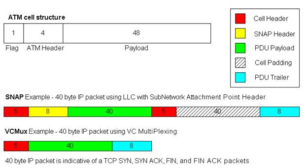
1.1 ATM AAL5 PDU Encapsulations
The following is an excerpt of RFC 2684 entitled ‘Multiprotocol Encapsulation over ATM Adaptation Layer 5’:
AAL5 PDU Format
For both multiplexing methods, routed and
bridged PDUs MUST be
encapsulated within
the Payload field of an AAL5 CPCS-PDU.
ITU-T Recommendation I.363.5 [2] provides
the complete definition of
the AAL5 PDU format
and procedures at the sender and receiver. The
AAL5 message mode service, in the
non-assured mode of operation MUST
be used. The
corrupted delivery option MUST NOT be used.
A
reassembly timer
MAY be used. The following description is provided
for information.
The format of the AAL5 CPCS-PDU is shown
below:
AAL5 CPCS-PDU Format
+-------------------------------+
| |
| |
|
CPCS-PDU Payload |
|
up to 2^16 - 1 octets) |
| |
| |
+-------------------------------+
|
PAD ( 0 - 47 octets) |
+-------------------------------+
-------
|
CPCS-UU (1 octet ) |
+-------------------------------+
|
CPI (1 octet )
|
+-------------------------------+CPCS-PDU Trailer
|
Length (2 octets) |
+-------------------------------|
|
CRC (4 octets) |
+-------------------------------+
-------
The Payload field contains user information
up to 2^16 - 1 octets.
The PAD field pads the CPCS-PDU to fit
exactly into the ATM cells
such that the last
48 octet cell payload created by the SAR sub layer
will have the
CPCS-PDU Trailer right justified in the cell.
Selection of the
Multiplexing Method
The decision as to whether to use LLC
encapsulation or VC-
multiplexing
depends on implementation and system requirements. In
general, LLC
encapsulation tends to require fewer VCs in a
multiprotocol
environment. VC multiplexing tends to
reduce
fragmentation
overhead (e.g., an IPV4 datagram containing a TCP
control packet with
neither IP nor TCP options exactly fits into a
single cell).
LLC SNAP Encapsulation
In LLC Encapsulation, the protocol type of
routed PDUs MUST be
identified by
prefixing an IEEE 802.2 LLC header to each PDU.
In
some cases, the LLC
header MUST be followed by an IEEE 802.1a
SubNetwork
Attachment Point (SNAP) header.
Although there is a NLPID value (0xCC) that
indicates IP, the NLPID
format MUST NOT be
used for IP. Instead, IP datagrams MUST
be
identified by a
SNAP header, as defined below.
Payload Format for Routed IPv4 PDUs
+-------------------------------+
|
LLC 0xAA-AA-03 |
+-------------------------------+
|
OUI 0x00-00-00 |
+-------------------------------+
|
EtherType 0x08-00 |
+-------------------------------+
| |
|
IPv4 PDU |
| (up to 2^16 - 9 octets) |
| |
+-------------------------------+
VC Multiplexing of Routed
Protocols
PDUs of routed
protocols MUST be carried as the only content of the
Payload of the AAL5
CPCS-PDU. The format of the AAL5
CPCS-PDU
Payload field thus becomes:
Payload Format for Routed PDUs
+-------------------------------+
|
Carried PDU |
| (up to 2^16 - 1 octets) |
+-------------------------------+
Applications of multiprotocol encapsulations Mutiprotocol
encapsulation is necessary, but generally not
sufficient, for
routing and bridging over the ATM networks.
Since
the publication of
RFC 1483 (the predecessor of this memo), several
system
specifications were developed by the IETF and the ATM Forum to
address various
aspects of, or scenarios for, bridged or routed
protocols. This appendix summarizes these applications.
1) Point-to-point
connection between routers and bridges
2) Classical IP over ATM --
RFC 2225 (formerly RFC 1577) provides an
environment where
the ATM network serves as a logical IP subnet.
3) LAN Emulation -- The ATM
Forum LAN Emulation specification
provides an
environment where the ATM network is enhanced by LAN
Emulation Server(s) to
behave as a bridged LAN.
4) Next Hop Resolution
Protocol (NHRP) -- In some cases, the
constraint that
Classical IP over ATM serve a single LIS limits
performance.
5) Multiprotocol
over ATM (MPOA) -- The ATM Forum Multiprotocol over
ATM Specification integrates LANE and NHRP
to provide a generic
bridging/routing
environment.
6) IP Multicast -- RFC 2022
extends Classical IP to support IP multicast.
7) PPP over ATM -- RFC 2364
extends multiprotocol over ATM to the
case where the
encapsulated protocol is the Point-to-Point
protocols.
Here is a set of diagrams
to show the LLC SNAP and VCMux PDU Formats:
1.2 Case Study
The graph that was created in this case study was designed to display the differences in bandwidth usage between Ethernet and ATM. The blue and the pink data points represent results from the same tests. The pink display the bps load on the ATM interface, and the blue represents the load on the GigEthernet interface in the same test iterations. In this case, the ATM AAL5 encapsulation used was VCMUX.
Here is an example of a real world test of am ATM OC-3 being tested using GigEthernet ports to saturated the interfaces:
Figure 1.2
Note that the ATM Interface usually is at or near 100% performance of the 149,760,000 bps that is it’s maximun capacity. So the ATM load is usually in the high 148 Mbps to the low 149 Mbps range. Whereas the Ethernet load ranges from 110 Mbps to 171 Mbps. That is quite a sweeping difference. And it has to do with how the IP packets are inserted into ATM cells using the AAL5 PDUs described earlier. The packet sizes selected where designed to hit the sweetest and the meanest spots for fitting packets in ATM Cells.
Take the example of the 106 byte and 107 byte IP Ethernet packets (Refer to Table 1.2). A 106 byte Ethernet packet will have the 18 byte IEEE Ethernet header removed when it arrives at the networking device. That leaves a 88 byte IP payload to be placed on the ATM wire. As this example used VCMUX to create AAL5 PDUs, only an 8 byte trailer is added to the 88 byte IP payload, creating a 96 byte PDU. By design, 96 bytes fits perfectly into 2 ATM cells without a single byte wasted in cell padding. So even though the ATM SAR mechanism wasn’t quite able to segment and reassemble packets at this size at 100% theoretical capacity (143.8 Mbps of 149.76 Mbps possible), a massive 171 Mbps load was carried on the Ethernet wire in the same instance.
In this rare instance, ATM was far more efficient than Ethernet at carrying the same number of packets. ATM used over 27 Mbps less bandwidth to transfer the same number of 106 byte IP Ethernet packets.
Ah, but then there is the 107 byte IP Ethernet packet. In the next case a single byte is added to the size of the packet, the whole comparison is flipped 180 degrees. With the 107 byte IP Ethernet packet, the same 18 bytes of Ethernet overhead is discarded and this time an 89 byte IP payload remains. The same 8 byte VCMux trailer is added creating a 97 byte PDU. Also by design, this barely misses being able to fit into two ATM cells and will require three ATM cells to be transported. Note that more data was actually able to be placed on the ATM wire (149.64 Mbps). That is 99.92% of theoretical line rate of 149.76 Mbps (OC-3 without SONET Overhead). So the ATM interface carried about as much as it theoretically could carry. But the load on the Ethernet wire is 119.52 Mbps in this instance. So in this case the Ethernet required 30 Mbps less than the ATM interface to carry the same number of packets. Naturally this is because the 107 byte IP Ethernet packet was 1 byte too big for two cells so all but 1 byte of the 3rd cell was wasted (52 or the 53 bytes).
That is quite a role reversal. To go from ATM being 27 Mbps more efficient than Ethernet to Ethernet being 30 Mbps more efficient than ATM with a difference of a single byte in the IP payload size. Now the 52 bytes that is wasted by adding the extra cell between the most efficient and least efficient IP payload sizes is constant, and as the packets get larger this extra 52 bytes incurred on ATM makes less and less of a difference. Certainly the difference in performance between a 106 byte IP Ethernet packets (171 Mbps) and 107 byte IP Ethernet packets (119.54 Mbps) is more dramatic than the difference between 1498 and 1499 byte IP Ethernet packets which are also selected to perfectly fit into 31 cells, and then to just miss 31 and require a 32nd cell to be transmitted. The 1498 byte IP Ethernet performance was 138.5 Mbps and the 1499 byte IP packet achieved 134 mbps. In both cases the ATM load was right around 149.76 Mbps. But the difference in Ethernet performance is less than 5 Mbps (compared to the 50 Mbps difference at the smaller packet size).
Obviously IP packets have variable length payloads and they are created by applications that rarely consider how well that packet will fit into ATM cells. But it is fair to say in looking at the comparison between the Ethernet load and the ATM load in the same test instances (Figure 1.2) that Ethernet tends to be more efficient than ATM (unless you are using some kind of VOIP application that creates nothing but 202 byte IP Ethernet packets). That is fairly unlikely.
For a good study of average Internet IP packet distributions, refer to the CAIDA website:
http://www.caida.org/outreach/papers/2003/nlanr/nlanr_overview.pdf
There is a great 3 year study based on data captured at 20 high performance Internet POPs.
Table 1.2 Data sheet that created the XY plot
displayed in Figure 1.2
|
ATM
AAL5 VCMUX Encapsulation |
|
|
|
||||
|
|
|
|
|
PPS x Packet Size x 8 =
bps |
|
||
|
Packet Size |
# ATM Cells |
PPS |
Cells |
ATM bps |
Line Rate |
% Line Rate Observed |
Ethernet bps |
|
64 |
2 |
163690 |
327380 |
138809120 |
149760000 |
92.68771368 |
109,999,680 |
|
106 |
2 |
169643 |
339286 |
143857264 |
149760000 |
96.05853632 |
171,000,144 |
|
107 |
3 |
117642 |
352926 |
149640624 |
149760000 |
99.92028846 |
119,524,272 |
|
128 |
3 |
117399 |
352197 |
149331528 |
149760000 |
99.71389423 |
139,000,416 |
|
154 |
3 |
117098 |
351294 |
148948656 |
149760000 |
99.45823718 |
163,000,416 |
|
155 |
4 |
87857 |
351428 |
149005472 |
149760000 |
99.49617521 |
122,999,800 |
|
202 |
4 |
88401 |
353604 |
149928096 |
149760000 |
100.1122436 |
157,000,176 |
|
203 |
5 |
70067 |
350335 |
148542040 |
149760000 |
99.18672543 |
124,999,528 |
|
250 |
5 |
70370 |
351850 |
149184400 |
149760000 |
99.61565171 |
151,999,200 |
|
251 |
6 |
58579 |
351474 |
149024976 |
149760000 |
99.50919872 |
126,999,272 |
|
256 |
6 |
58877 |
353262 |
149783088 |
149760000 |
100.0154167 |
130,000,416 |
|
298 |
6 |
58569 |
351414 |
148999536 |
149760000 |
99.49221154 |
148,999,536 |
|
299 |
7 |
50157 |
351099 |
148865976 |
149760000 |
99.40302885 |
128,000,664 |
|
346 |
7 |
50205 |
351435 |
149008440 |
149760000 |
99.49815705 |
147,000,240 |
|
347 |
8 |
43937 |
351496 |
149034304 |
149760000 |
99.51542735 |
128,999,032 |
|
394 |
8 |
44082 |
352656 |
149526144 |
149760000 |
99.84384615 |
145,999,584 |
|
395 |
9 |
39157 |
352413 |
149423112 |
149760000 |
99.77504808 |
130,001,240 |
|
442 |
9 |
39232 |
353088 |
149709312 |
149760000 |
99.96615385 |
145,001,472 |
|
443 |
10 |
35097 |
350970 |
148811280 |
149760000 |
99.36650641 |
129,999,288 |
|
490 |
10 |
35294 |
352940 |
149646560 |
149760000 |
99.92425214 |
143,999,520 |
|
491 |
11 |
32045 |
352495 |
149457880 |
149760000 |
99.79826389 |
130,999,960 |
|
538 |
11 |
32034 |
352374 |
149406576 |
149760000 |
99.76400641 |
142,999,776 |
|
539 |
12 |
29293 |
351516 |
149042784 |
149760000 |
99.52108974 |
130,998,296 |
|
586 |
12 |
29290 |
351480 |
149027520 |
149760000 |
99.51089744 |
141,997,920 |
|
587 |
13 |
27183 |
353379 |
149832696 |
149760000 |
100.0485417 |
132,000,648 |
|
634 |
13 |
27141 |
352833 |
149601192 |
149760000 |
99.89395833 |
142,001,712 |
|
635 |
14 |
25191 |
352674 |
149533776 |
149760000 |
99.84894231 |
132,000,840 |
|
682 |
14 |
25107 |
351498 |
149035152 |
149760000 |
99.51599359 |
141,000,912 |
|
683 |
15 |
23471 |
352065 |
149275560 |
149760000 |
99.67652244 |
132,000,904 |
|
730 |
15 |
23500 |
352500 |
149460000 |
149760000 |
99.79967949 |
141,000,000 |
|
731 |
16 |
21971 |
351536 |
149051264 |
149760000 |
99.52675214 |
132,001,768 |
|
778 |
16 |
22086 |
353376 |
149831424 |
149760000 |
100.0476923 |
140,997,024 |
|
779 |
17 |
20651 |
351067 |
148852408 |
149760000 |
99.39396902 |
132,001,192 |
|
826 |
17 |
20686 |
351662 |
149104688 |
149760000 |
99.56242521 |
140,002,848 |
|
827 |
18 |
19628 |
353304 |
149800896 |
149760000 |
100.0273077 |
132,999,328 |
|
874 |
18 |
19634 |
353412 |
149846688 |
149760000 |
100.0578846 |
140,422,368 |
|
875 |
19 |
18575 |
352925 |
149640200 |
149760000 |
99.92000534 |
132,997,000 |
|
922 |
19 |
18577 |
352963 |
149656312 |
149760000 |
99.93076389 |
139,996,272 |
|
923 |
20 |
17630 |
352600 |
149502400 |
149760000 |
99.82799145 |
133,000,720 |
|
970 |
20 |
17551 |
351020 |
148832480 |
149760000 |
99.38066239 |
139,003,920 |
|
971 |
21 |
16776 |
352296 |
149373504 |
149760000 |
99.74192308 |
133,000,128 |
|
1018 |
21 |
16739 |
351519 |
149044056 |
149760000 |
99.5219391 |
139,000,656 |
|
1019 |
22 |
16001 |
352022 |
149257328 |
149760000 |
99.66434829 |
133,000,312 |
|
1024 |
22 |
16044 |
352968 |
149658432 |
149760000 |
99.93217949 |
133,999,488 |
|
1066 |
22 |
15999 |
351978 |
149238672 |
149760000 |
99.65189103 |
138,999,312 |
|
1067 |
23 |
15294 |
351762 |
149147088 |
149760000 |
99.59073718 |
132,996,624 |
|
1114 |
23 |
15322 |
352406 |
149420144 |
149760000 |
99.77306624 |
139,001,184 |
|
1115 |
24 |
14648 |
351552 |
149058048 |
149760000 |
99.53128205 |
133,003,840 |
|
1162 |
24 |
14700 |
352800 |
149587200 |
149760000 |
99.88461538 |
139,003,200 |
|
1163 |
25 |
14053 |
351325 |
148961800 |
149760000 |
99.46701389 |
132,997,592 |
|
1210 |
25 |
14126 |
353150 |
149735600 |
149760000 |
99.98370726 |
138,999,840 |
|
1211 |
26 |
13505 |
351130 |
148879120 |
149760000 |
99.41180556 |
132,997,240 |
|
1258 |
26 |
13595 |
353470 |
149871280 |
149760000 |
100.0743056 |
138,995,280 |
|
1259 |
27 |
13090 |
353430 |
149854320 |
149760000 |
100.0629808 |
133,936,880 |
|
1306 |
27 |
13086 |
353322 |
149808528 |
149760000 |
100.0324038 |
138,816,288 |
|
1307 |
28 |
12622 |
353416 |
149848384 |
149760000 |
100.0590171 |
133,995,152 |
|
1354 |
28 |
12626 |
353528 |
149895872 |
149760000 |
100.0907265 |
138,784,992 |
|
1355 |
29 |
12182 |
353278 |
149789872 |
149760000 |
100.0199466 |
134,002,000 |
|
1402 |
29 |
12189 |
353481 |
149875944 |
149760000 |
100.0774199 |
138,662,064 |
|
1403 |
30 |
11771 |
353130 |
149727120 |
149760000 |
99.97804487 |
134,001,064 |
|
1450 |
30 |
11787 |
353610 |
149930640 |
149760000 |
100.1139423 |
138,615,120 |
|
1451 |
31 |
11387 |
352997 |
149670728 |
149760000 |
99.94038996 |
134,002,216 |
|
1498 |
31 |
11405 |
353555 |
149907320 |
149760000 |
100.0983707 |
138,502,320 |
|
1499 |
32 |
11027 |
352864 |
149614336 |
149760000 |
99.90273504 |
134,000,104 |
|
1518 |
32 |
10972 |
351104 |
148868096 |
149760000 |
99.40444444 |
134,999,488 |
Richard Hay
Systems Engineer
rhay@tamos.net